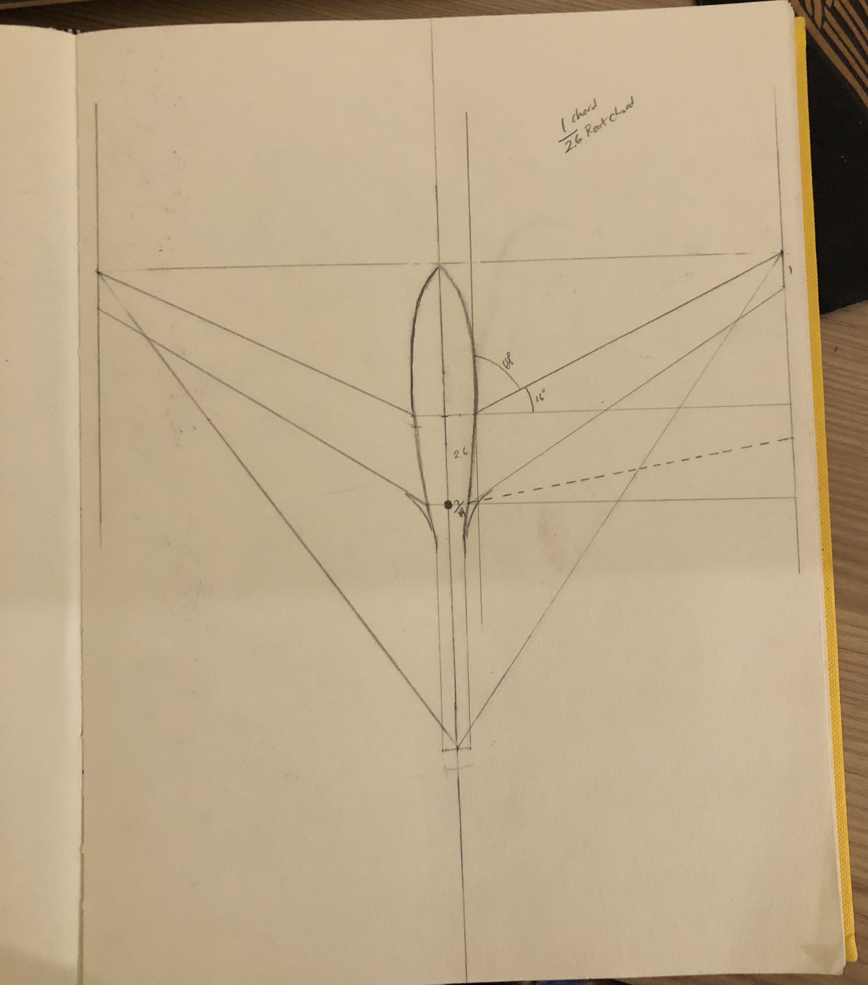
Drawing: Most of my ideas in engineering begin as a simple drawing. This project was no different, and it started with a sketch of the top and side profile of the craft.
VTOL Drone Personal Project
During the summer of 2023, in the evenings after my work at JPL, I pursued
an idea that had been lingering with me for quite a while. I noticed that if
a VTOL tilt-rotor drone could be designed with a forward sweep, it would allow for a design that
could place motors and servos in an ideal location. Using a hybrid-composite design, three motors and three tilt
mechanisms respectively, I built my own control scheme based off the dRhem Flight VTOL scheme and added an
optical flow sensor for stationkeeping.
I created an initial prototype of the VTOL and completed some testing before my final year of undergrad.

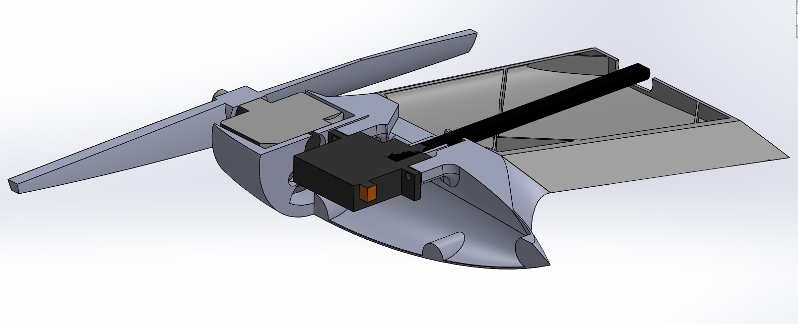
Design: The design of the UAV was designed fully in Solidworks, featuring a forward-swept wing with two tilt motors on the sides.
These tilt motors are not only used for VTOL transition but also serve as the primary roll control for the craft.
In addition to these tip tilt motors, the craft has a third tilt motor at the rear that increases overall payload capacity
and serves as the main thruster during forward flight. The tail is also in a V-tail configuration, saving on weight and improving efficiency.
The design also places emphasis on aesthetics, with smooth lines and intersections, and a sleek profile that enhances not only
the aerodynamic performance but also the overall visual appeal of the craft.

Layout and Analysis: The layout is a triangular tricopter design, which has been proven as a successful configuration for small-scale drones in the past. There are also a series of five servos for control of the tilt mechanisms and the elevons. In hover, servos 1 and 2 are responsible for yaw, while in forward flight they control roll. Servos 4 and 5 control the elevons. Servo 3 operates the rear tilt motor, yet it is placed closer to the center to optimize the CG location.

The Build: The build was done using an Ender 3 3D printer with both foaming PLA (LW-PLA) and carbon composite PETG. The full CAD of the system was designed to be easily manufacturable through 3D printing, as it was the most accessible method of manufacture to me at the time.
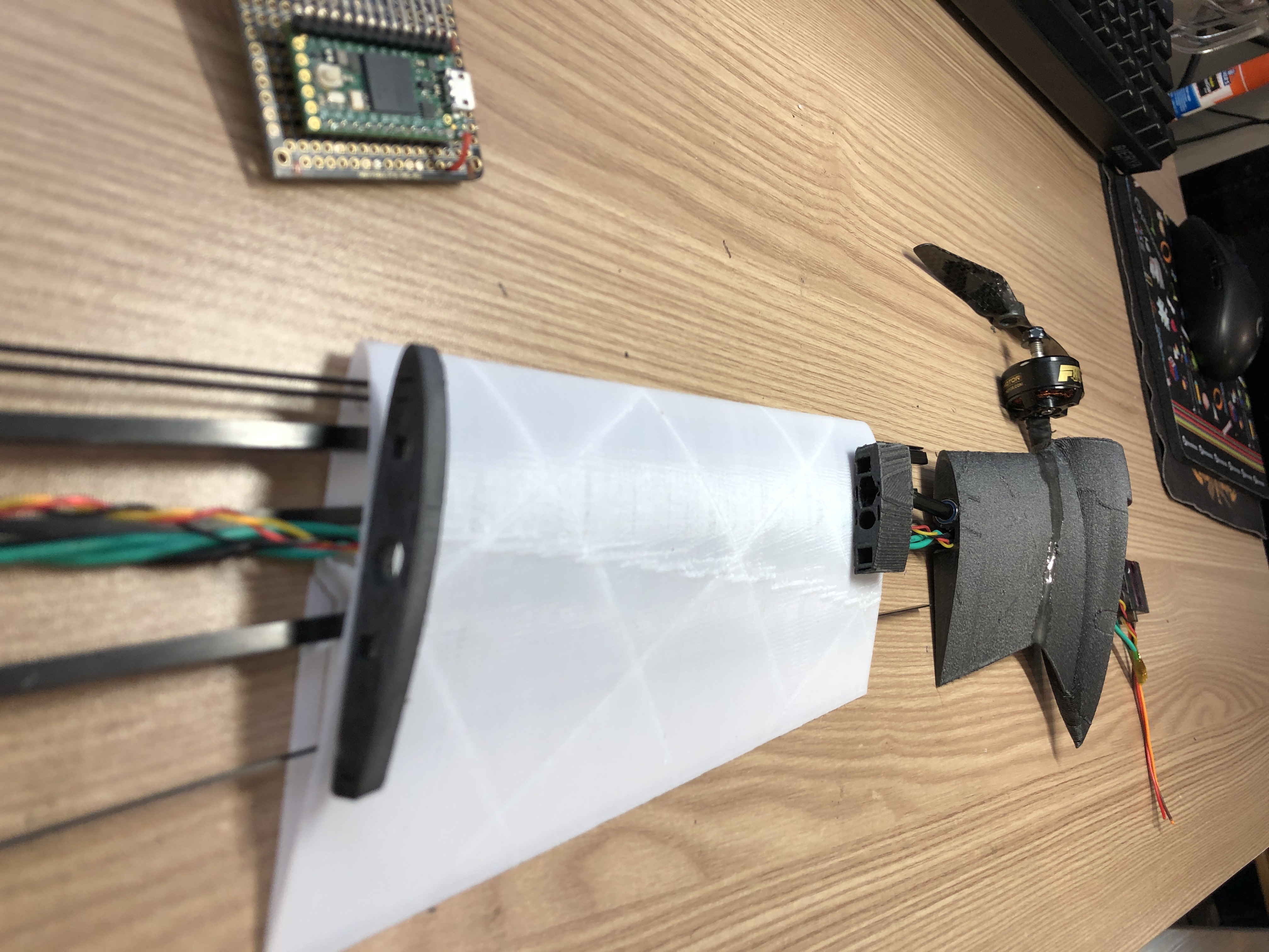
Wingtip Tilt Mechanism: The wingtip tilt mechanism was custom designed to allow rotation of the motor’s thrust axis. The internal system needed a servo to control this tilt, space for wires to pass through, and bearings to support the shaft that connects the servo to the fixed wing.
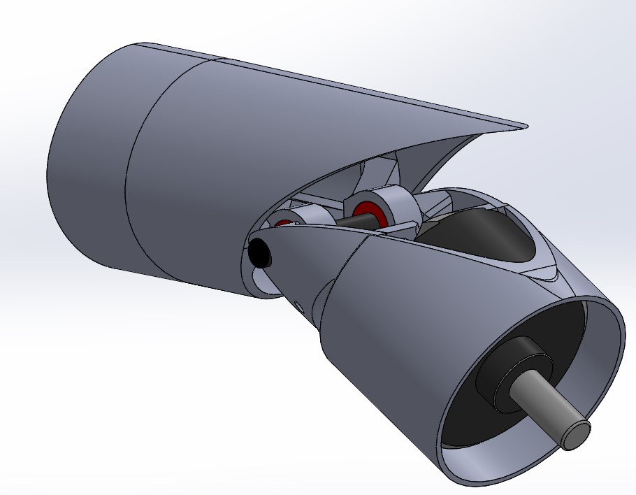
Rear Tilt Mechanism: The design features an intricate joint mechanism paired with an attachment point for the internal servo control rod. With its small form factor for aerodynamics and aesthetics, this mechanism was a challenge to manufacture on the 3D printer.
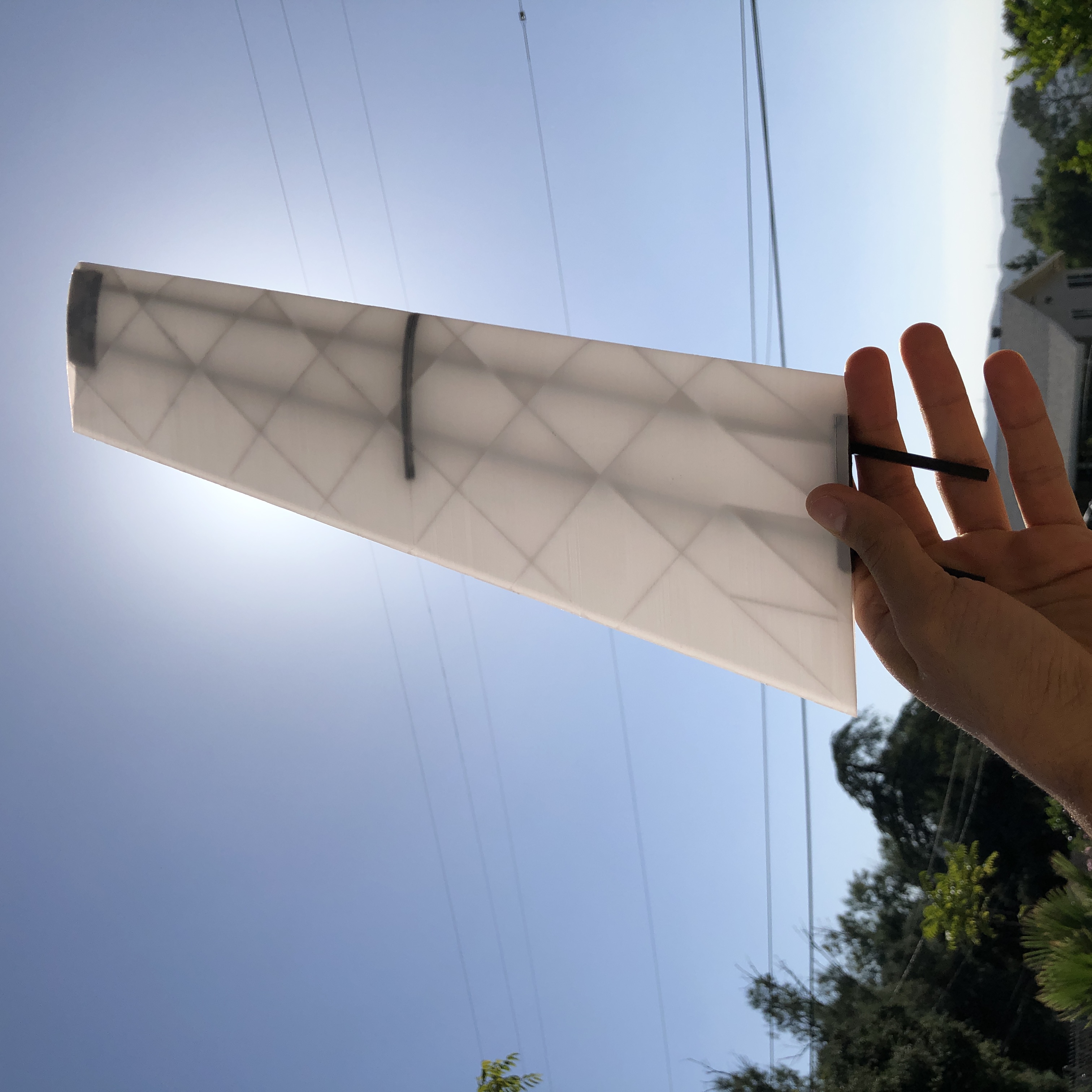
Wing Design: Notorious for aeroelastic divergence that causes unstable flutter, a high-stiffness wing was needed. With the added inertia of the motors, the craft was even further pushed to have an extremely stiff wing. This prompted a hybrid composite design approach, utilizing both 3D-printed and carbon fiber elements. The wings feature a complex internal structure optimized for lateral and torsional stiffness while still being lightweight. This 3D-printed structure wraps around a carbon skeleton optimized for torsional stiffness and load-bearing capacity.
Wing Design Continued: The internal structure of the wing was also a challenge to design and build. The dense carbon fiber skeleton and internal wiring were difficult to achieve within the bounds of the airfoil optimized for aerodynamic performance. Combined with the loads from the motor mount at the wingtip, the wing itself became a very complex aerodynamic member.
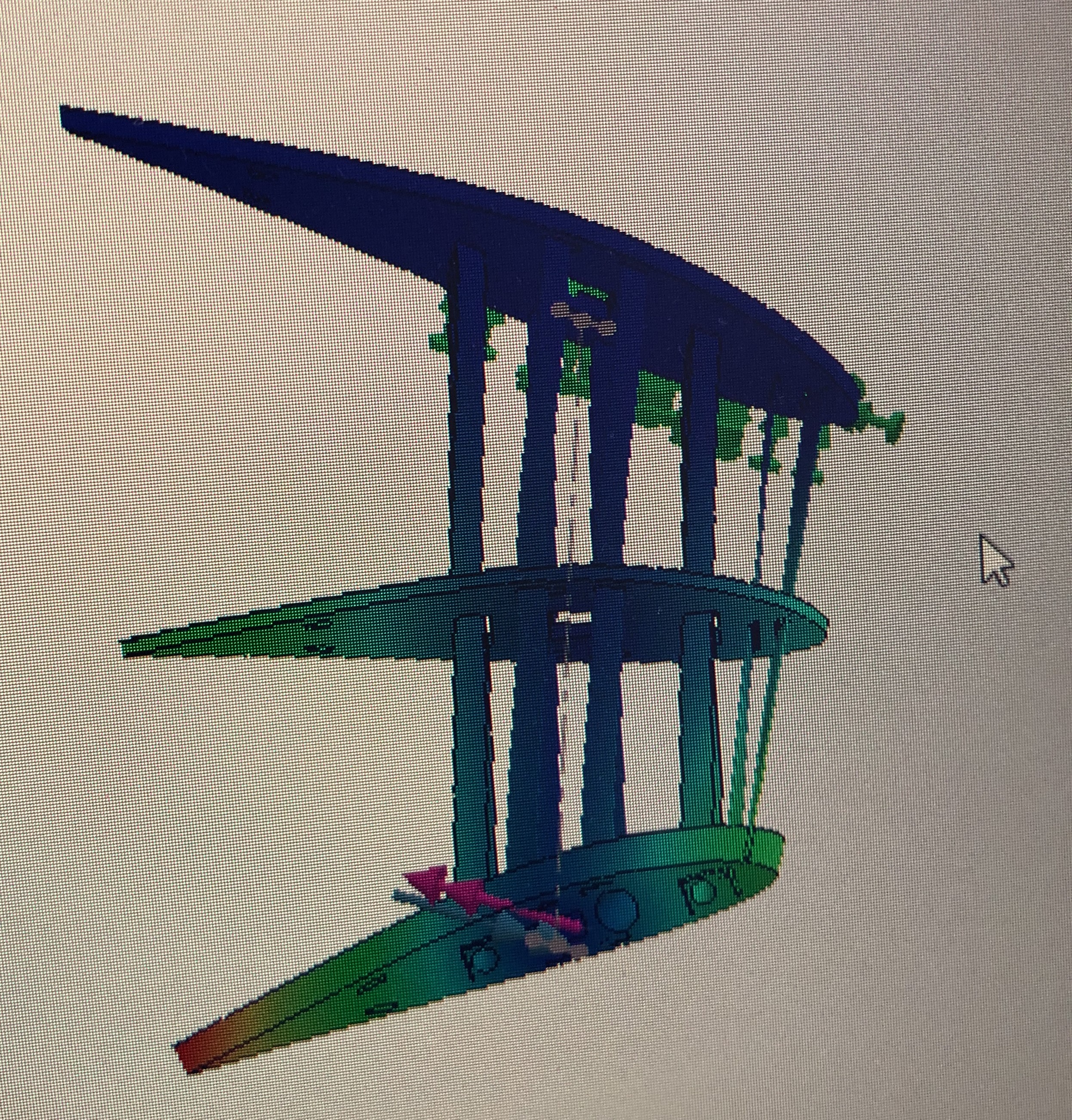
FEA: I ran finite element analysis on the wing to ensure the design was robust enough to handle the loads I had calculated through analysis.
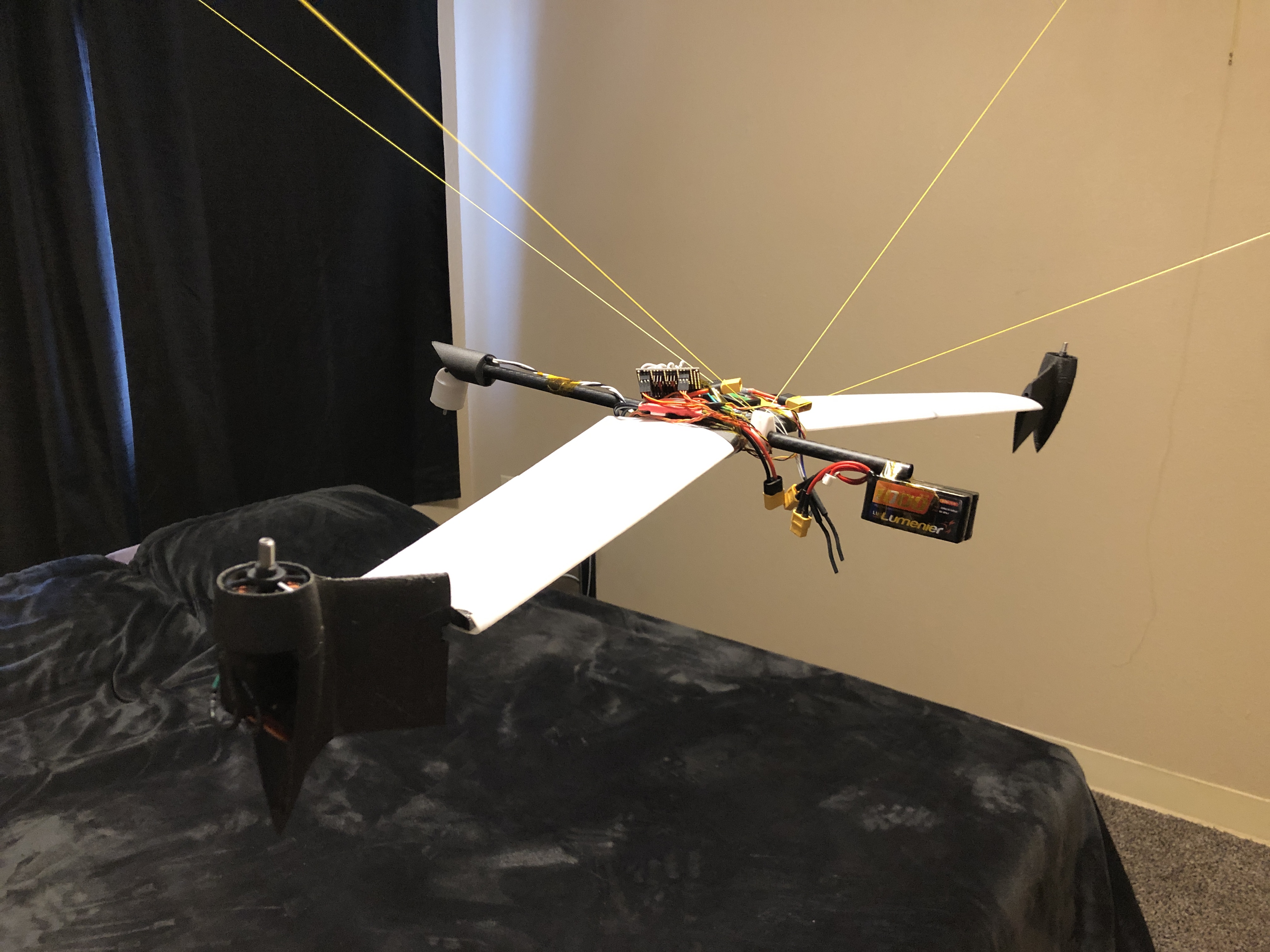
Testing: Testing of the craft was done within the bounds of my own bedroom. I created a simple setup by suspending the craft with strings. This allowed me to tune the control system and test various mixes of pitch, yaw, and roll control in hover.
Testing the wingtip tilt-rotor!
Overall, although unfinished, the project was a success in terms of what I learned and the experience I gained. I was frequently humbled by the challenges, especially in integration, and with each subsystem — avionics, controls, and mechanisms — there were always one or two obstacles that were especially tough.